
Demo Room
Kacper2026-04-28T09:42:26+00:00QUICK Demo Room
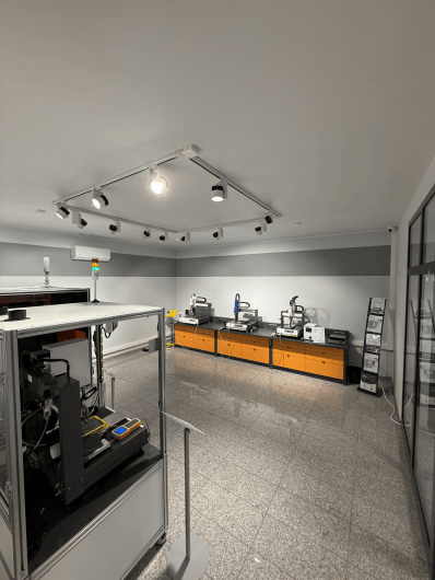
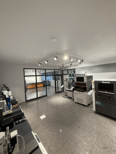
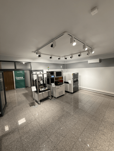
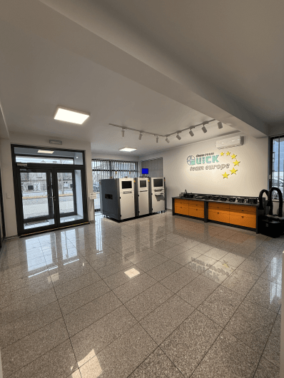
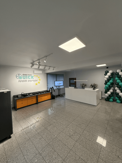
QUICK Demo Room – Soldering Technology Centre
Visit the QUICK Soldering Technology Centre and explore laser soldering, AOI inspection, selective wave soldering, hot-bar systems and automation solutions in real operating conditions.

Welcome to the QUICK Demo Room – our Soldering Technology Centre!
The first QUICK Demo Room in Europe is now open.
Watch the video from the opening event and see what is available in our demonstration area. During a visit, we can present selected QUICK systems in operation and discuss their use in real production processes.
The QUICK Demo Room gives you access to a wide range of technologies for electronics manufacturing, including AOI inspection systems, selective wave soldering, laser soldering, hot-bar systems, Cartesian soldering robots, dispensing robots and screw-driving robots. The area also includes classic soldering stations, fume extraction systems and ESD protection equipment.
Book a visit and see the equipment in action.
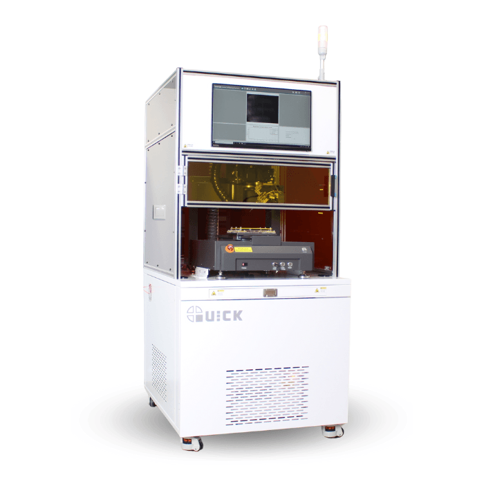
QUICK LW10 – Laser soldering machine with wire-fed soldering technology
Explore more laser soldering solutions in our catalogue:
Description
Laser soldering with controlled wire feed
The QUICK LW10 uses a laser beam as a focused heat source and solder wire as the solder material. This makes it suitable for selective, contactless soldering where repeatability, thermal control and access to small solder joints are important.
The system combines closed-loop temperature control, vision-assisted positioning, system temperature sensing and a coaxial optical path for process monitoring. It is designed for precise soldering processes in electronics manufacturing, especially where stable heat input and controlled solder wire feeding are required.
Key features
- Real-time soldering temperature measurement for closed-loop process control.
- High-precision solder wire feeder with alarms for missing or broken solder wire.
- Optional solder wire notching/grooving function.
- Adjustable wire-feed holder height for different pad sizes and solder joint geometries.
- Optical lens sets for real-time monitoring of the soldering process.
- Coaxial CCD camera for positioning, process observation and alignment calibration.
- Laser, CCD camera and temperature measurement arranged in a coaxial configuration to simplify optical path alignment.
- User-friendly software suitable for various laser soldering applications.
Specifications
| Model | LW10 |
|---|---|
| General | |
| Power supply | 220 V, 50 Hz / 60 Hz |
| Air supply | 0–0.5 MPa |
| Peak power | 2500 W |
| Weight | 500 kg |
| Dimensions | 850 × 930 × 1900 mm |
| Soldering module operating range | X: 300 mm, Y: 300 mm, Z: 100 mm |
| Accuracy | |
| Repeatability X/Y/Z | ±0.01 mm |
| Positioning accuracy X/Y/Z | ±0.02 mm |
| Laser | |
| Power | 100 W |
| Wavelength | 915 nm |
Ask about this product:
Laser soldering with controlled wire feed
The QUICK LW10 uses a laser beam as a focused heat source and solder wire as the solder material. This makes it suitable for selective, contactless soldering where repeatability, thermal control and access to small solder joints are important.The system combines closed-loop temperature control, vision-assisted positioning, system temperature sensing and a coaxial optical path for process monitoring. It is designed for precise soldering processes in electronics manufacturing, especially where stable heat input and controlled solder wire feeding are required.Key features
- Real-time soldering temperature measurement for closed-loop process control.
- High-precision solder wire feeder with alarms for missing or broken solder wire.
- Optional solder wire notching/grooving function.
- Adjustable wire-feed holder height for different pad sizes and solder joint geometries.
- Optical lens sets for real-time monitoring of the soldering process.
- Coaxial CCD camera for positioning, process observation and alignment calibration.
- Laser, CCD camera and temperature measurement arranged in a coaxial configuration to simplify optical path alignment.
- User-friendly software suitable for various laser soldering applications.
Specifications
| Model | LW10 |
|---|---|
| General | |
| Power supply | 220 V, 50 Hz / 60 Hz |
| Air supply | 0–0.5 MPa |
| Peak power | 2500 W |
| Weight | 500 kg |
| Dimensions | 850 × 930 × 1900 mm |
| Soldering module operating range | X: 300 mm, Y: 300 mm, Z: 100 mm |
| Accuracy | |
| Repeatability X/Y/Z | ±0.01 mm |
| Positioning accuracy X/Y/Z | ±0.02 mm |
| Laser | |
| Power | 100 W |
| Wavelength | 915 nm |
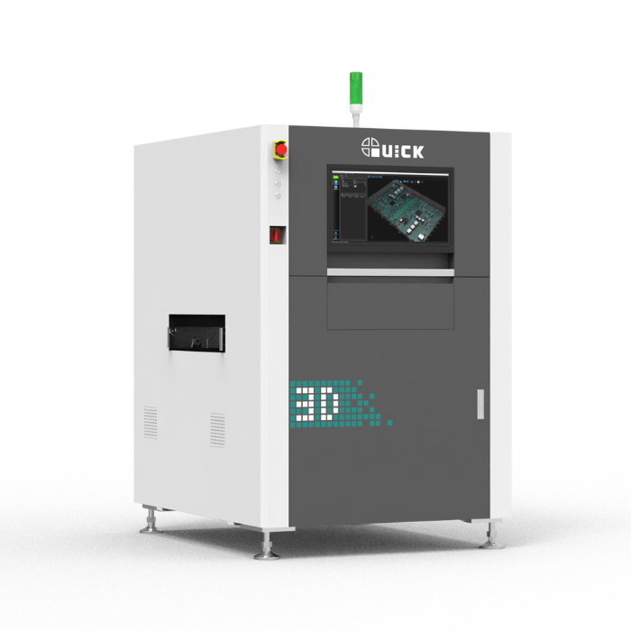
QUICK 3D AOI A300T – automated 3D optical inspection system for PCB assemblies
Explore more AOI solutions in our catalogue:
Description
QUICK 3D AOI A300T
QUICK 3D AOI A300T is an automated 3D optical inspection system designed to detect soldering and assembly defects on PCB assemblies. Advanced image analysis supports reliable quality control in electronics manufacturing.Key features
- Fast and precise linear-motor platform.
- Advanced 3D reconstruction algorithm for accurate 3D inspection data.
- High-angle 4/8 projection to effectively reduce shadow effects.
- Combined 2D and 3D inspection algorithms for reliable defect detection.
- Adaptive colour algorithm resistant to different PCB colours.
- Multi-position dynamic height reference algorithm to compensate for PCB warpage.
Specifications
| Model | QUICK 3D AOI A300T |
|---|---|
| Optical imaging system | |
| Camera | 12 MP high-speed camera |
| Light source | Multi-angle RGBW light source, four-direction projection |
| Optical resolution | 10 μm / 15 μm |
| Inspection speed | 450 ms/FOV |
| Defect inspection | |
| Component defects | Misalignment, missing component, skew, tombstoning, reversed component, flipped component, wrong component, damaged component, polarity |
| Solder joint defects | Solder projections, blowholes, solder balls, insufficient solder, excess solder, solder bridge, deformed lead, contamination/scratches on gold fingers |
| General | |
| Application | SMT inspection before and after reflow |
| Programming mode | Manual programming, CAD data import, AI programming |
| X-Y axis control system | Linear-motor drive |
| X-Y positioning accuracy | 5 μm |
| PCB carrier size | 50 × 50 mm (Min.) ~ 510 × 500 mm (Max.) |
| PCB warpage | <5 mm |
| Measurable PCB thickness | 0.6–5 mm |
| PCB conveyor height | 880–920 mm |
| PCB flow direction | Left-to-right or right-to-left, factory setting |
| Maximum conveyor load | 5 kg |
| Conveyor width adjustment and transport | Automatic width adjustment, belt transport |
| Maximum component height | 45 mm top / 60 mm bottom |
| Weight | 900 kg |
| Dimensions | 1000 × 1500 × 1650 mm |
| Power supply | 200–240 V, single-phase, 50/60 Hz, 3 kVA |
| Air supply | 5–6 bar |
| Safety | CE compliant |
| Software | Offline programming software as standard, maintenance station as standard, optional SPC management system, MES integration |
Ask about this product:
QUICK 3D AOI A300T
QUICK 3D AOI A300T is an automated 3D optical inspection system designed to detect soldering and assembly defects on PCB assemblies. Advanced image analysis supports reliable quality control in electronics manufacturing.Key features
- Fast and precise linear-motor platform.
- Advanced 3D reconstruction algorithm for accurate 3D inspection data.
- High-angle 4/8 projection to effectively reduce shadow effects.
- Combined 2D and 3D inspection algorithms for reliable defect detection.
- Adaptive colour algorithm resistant to different PCB colours.
- Multi-position dynamic height reference algorithm to compensate for PCB warpage.
Specifications
| Model | QUICK 3D AOI A300T |
|---|---|
| Optical imaging system | |
| Camera | 12 MP high-speed camera |
| Light source | Multi-angle RGBW light source, four-direction projection |
| Optical resolution | 10 μm / 15 μm |
| Inspection speed | 450 ms/FOV |
| Defect inspection | |
| Component defects | Misalignment, missing component, skew, tombstoning, reversed component, flipped component, wrong component, damaged component, polarity |
| Solder joint defects | Solder projections, blowholes, solder balls, insufficient solder, excess solder, solder bridge, deformed lead, contamination/scratches on gold fingers |
| General | |
| Application | SMT inspection before and after reflow |
| Programming mode | Manual programming, CAD data import, AI programming |
| X-Y axis control system | Linear-motor drive |
| X-Y positioning accuracy | 5 μm |
| PCB carrier size | 50 × 50 mm (Min.) ~ 510 × 500 mm (Max.) |
| PCB warpage | <5 mm |
| Measurable PCB thickness | 0.6–5 mm |
| PCB conveyor height | 880–920 mm |
| PCB flow direction | Left-to-right or right-to-left, factory setting |
| Maximum conveyor load | 5 kg |
| Conveyor width adjustment and transport | Automatic width adjustment, belt transport |
| Maximum component height | 45 mm top / 60 mm bottom |
| Weight | 900 kg |
| Dimensions | 1000 × 1500 × 1650 mm |
| Power supply | 200–240 V, single-phase, 50/60 Hz, 3 kVA |
| Air supply | 5–6 bar |
| Safety | CE compliant |
| Software | Offline programming software as standard, maintenance station as standard, optional SPC management system, MES integration |
Explore more selective soldering solutions in our catalogue:
Description
Key features
- Modular design with flexible configuration options.
- Maximum PCB size: 405 × 405 mm.
- Suitable for both high-volume and small-batch production.
- Fast, simple and efficient programming by defining soldering paths based on images.
- Convenient visual application with automatic scanning and alignment.
Specifications
| Model | QUICK W4040 |
|---|---|
| Machine specifications | |
| Motion range | 405 × 405 mm |
| Functional area | Single soldering module with a single solder pot |
| Power supply | 3-phase 380 V, 50 Hz / max. power 24 kW |
| Air supply | Compressed air >0.6 MPa / nitrogen >0.3 MPa |
| Dimensions | 2480 × 1600 × 1600 mm, excluding PC or signal tower |
| Weight | Approx. 1800 kg |
| Communication | SMEMA standard |
| Conveyor specifications | |
| Conveyor height | 900 ±50 mm |
| Max. overboard clearance | 100 mm |
| Max. underboard clearance | 60 mm |
| Conveyor width | 70–405 mm |
| Functional station specifications | |
| Fluxing method | Micro-droplet jet, spot spray / line spray |
| CCD visual alignment of flux spray module | Automatic fiducial point recognition for position compensation |
| Heating method | IR / hot air |
| Pump | Electromagnetic pump |
| Wave height | 0–5 mm |
| Wave height measurement | Automatic |
| Solder pot capacity | 13 kg |
| Max. solder pot temperature | ≤330 °C |
| Soldering process monitoring system | CCD real-time display function |
| Programming mode | Online visual programming using images or Gerber files, offline programming / CCD scanning |
Ask about this product:
Key features
- Modular design with flexible configuration options.
- Maximum PCB size: 405 × 405 mm.
- Suitable for both high-volume and small-batch production.
- Fast, simple and efficient programming by defining soldering paths based on images.
- Convenient visual application with automatic scanning and alignment.
Specifications
| Model | QUICK W4040 |
|---|---|
| Machine specifications | |
| Motion range | 405 × 405 mm |
| Functional area | Single soldering module with a single solder pot |
| Power supply | 3-phase 380 V, 50 Hz / max. power 24 kW |
| Air supply | Compressed air >0.6 MPa / nitrogen >0.3 MPa |
| Dimensions | 2480 × 1600 × 1600 mm, excluding PC or signal tower |
| Weight | Approx. 1800 kg |
| Communication | SMEMA standard |
| Conveyor specifications | |
| Conveyor height | 900 ±50 mm |
| Max. overboard clearance | 100 mm |
| Max. underboard clearance | 60 mm |
| Conveyor width | 70–405 mm |
| Functional station specifications | |
| Fluxing method | Micro-droplet jet, spot spray / line spray |
| CCD visual alignment of flux spray module | Automatic fiducial point recognition for position compensation |
| Heating method | IR / hot air |
| Pump | Electromagnetic pump |
| Wave height | 0–5 mm |
| Wave height measurement | Automatic |
| Solder pot capacity | 13 kg |
| Max. solder pot temperature | ≤330 °C |
| Soldering process monitoring system | CCD real-time display function |
| Programming mode | Online visual programming using images or Gerber files, offline programming / CCD scanning |
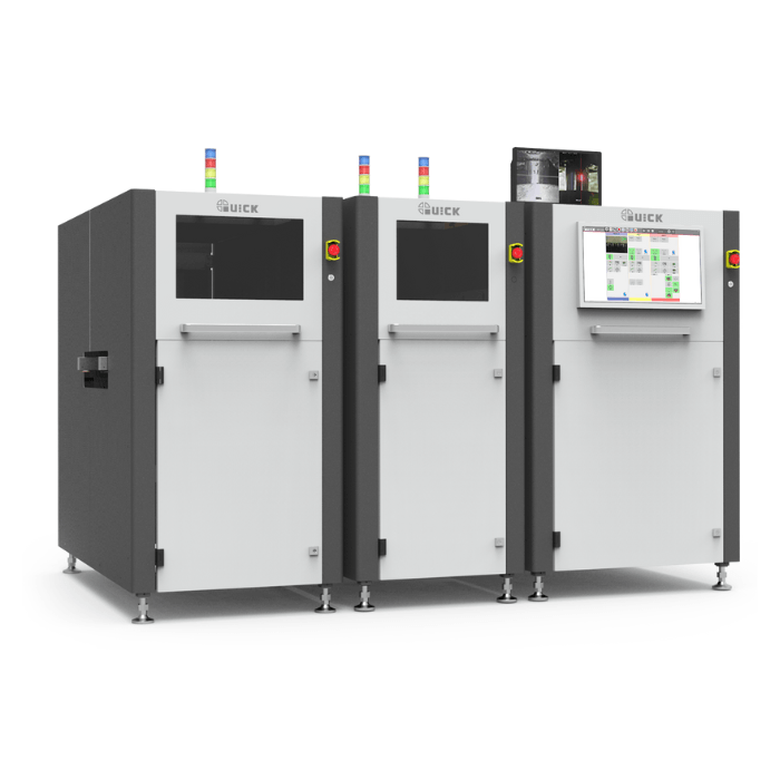
Explore more hot-bar soldering solutions in our catalogue:
Description
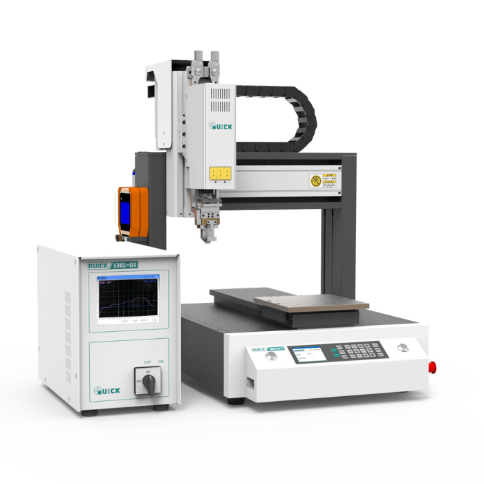
Motion platform
The Y axis is driven by a closed-loop motor with high load capacity and precise speed control. Dual rails on the X/Y axes ensure accurate movement. Multiple soldering process parameter groups can be selected, read by the MES system and started with two-hand operation, with optional one-hand or two-hand start modes for improved safety and reliability.Heating controller
The intelligent temperature control system provides accurate and stable temperature regulation with closed-loop control. RS485 communication enables connection to a PC or PLC, while abnormal temperature conditions can trigger an alarm.Pressure control
The closed-loop pressure control system includes an alarm function for abnormal conditions. Real-time pressure monitoring allows precise adjustment of soldering process parameters, supporting consistent soldering quality and reliable solder joints.Operator panel
The 9011D operator panel supports board and group functions, making it easier to handle fixture deviations and tip replacement. It supports different processing modes, including simultaneous operation, full-board processing, simulated operation and cyclic automatic processing. This gives the operator better control over the soldering process and makes it easier to adapt to changing production requirements.
Specifications
| Model | QUICK ET9H393 |
|---|---|
| Technical parameters | |
| Number of axes | 3 |
| Power consumption | 200 W |
| Heating controller power consumption | 1500 W |
| Motion range | |
| X/Y axis | 300 mm |
| Z axis | 100 mm |
| Motion speed | |
| X/Y axis | 0.1–600 mm/s |
| Z axis | 0.1–300 mm/s |
| Repeatability | |
| X/Y/Z axis | ±0.02 mm |
| General | |
| Working area | 300 × 300 mm |
| Dimensions | 480 × 530 × 670 mm, without heating controller |
| Weight | To be verified — source value appears incorrect: 300 × 300 mm |
Ask about this product:
Motion platform
The Y axis is driven by a closed-loop motor with high load capacity and precise speed control. Dual rails on the X/Y axes ensure accurate movement. Multiple soldering process parameter groups can be selected, read by the MES system and started with two-hand operation, with optional one-hand or two-hand start modes for improved safety and reliability.Heating controller
The intelligent temperature control system provides accurate and stable temperature regulation with closed-loop control. RS485 communication enables connection to a PC or PLC, while abnormal temperature conditions can trigger an alarm.Pressure control
The closed-loop pressure control system includes an alarm function for abnormal conditions. Real-time pressure monitoring allows precise adjustment of soldering process parameters, supporting consistent soldering quality and reliable solder joints.Operator panel
The 9011D operator panel supports board and group functions, making it easier to handle fixture deviations and tip replacement. It supports different processing modes, including simultaneous operation, full-board processing, simulated operation and cyclic automatic processing. This gives the operator better control over the soldering process and makes it easier to adapt to changing production requirements.Specifications
| Model | QUICK ET9H393 |
|---|---|
| Technical parameters | |
| Number of axes | 3 |
| Power consumption | 200 W |
| Heating controller power consumption | 1500 W |
| Motion range | |
| X/Y axis | 300 mm |
| Z axis | 100 mm |
| Motion speed | |
| X/Y axis | 0.1–600 mm/s |
| Z axis | 0.1–300 mm/s |
| Repeatability | |
| X/Y/Z axis | ±0.02 mm |
| General | |
| Working area | 300 × 300 mm |
| Dimensions | 480 × 530 × 670 mm, without heating controller |
| Weight | To be verified — source value appears incorrect: 300 × 300 mm |